Electric motor drive
Electric motors were designed-in for the ease of handling and speed of calculation (see introduction). You perhaps have asked yourself how this is done. Especially mechanical calculators, who have machine cycles of one turn and those machines who have a reciprocal driving, they use only a part of the 360 degrees turn. Electric motors are good in rotary driving and make many turns per minute.
In this chapter I will show a few mechanisms which are used for that purpose.
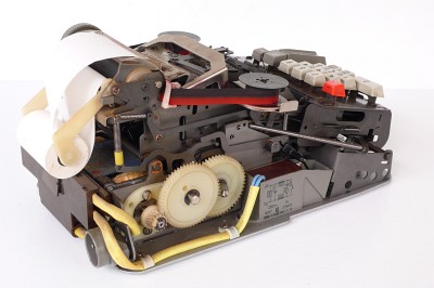
As introduction / first impression two examples of electrical driven machines are shown below, followed by details of the drive mechanisms used:
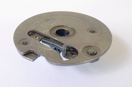
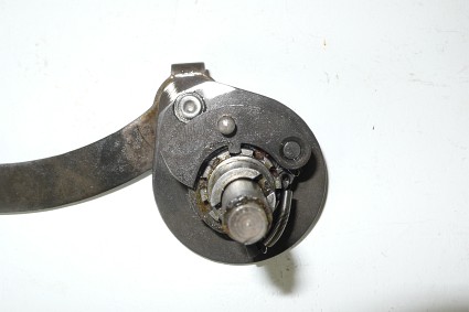
The black plate can be used to uncouple the motor for maintenance or examination / analyzing of failures useful to make use of. This can be done to shift the black plate counter clockwise, so that the lever does right that. This plate can be reached from the front side via a hole in the plate.
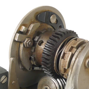
We see here the demounted motor unit from the back side, this side is mounted to the main machine axis.
The front and back plate are fixed together. The here front plate will be mounted on the machine axis. The left picture shows the rest position. You noticed the worm gear combination and the clutch. The back plate is released by the standing lever (red arrow) which controls the catch and trap. When the catch is trapped the motor turns the back and front plate. When the catch is not trapped the motor is free running and the plates stand still.
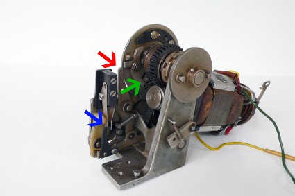
Now the whole sequence. The first pictures is in the parking situation. On the second picture: the plate stop standing lever is set aside (red arrow), the catch is pushed in the trap (green arrow) and the electrical switch is switched on (blue arrow), which all is initiated by a pressed action key (Plus; Minus or Total key etc) of the key board.
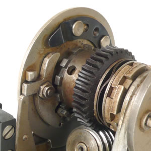
The same pictures as above again below. The left one, is the situation just before the end of the turn is initiated. The catch is still trapped. The right one below the rest position is shown.
It pushes the electrical motor switch off, the standing lever is pushed to the stop position again, the catch is pulled out of the trap and will stop the machine axis from turning and the motor roll out.
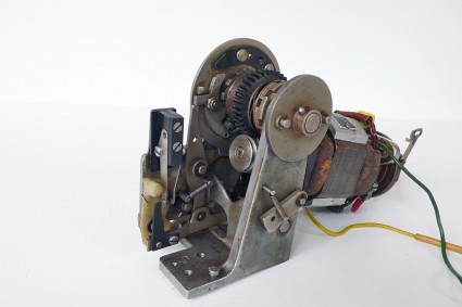
First action is reducing the speed and in the meantime increasing the force of the axis which drives the machine. The motors applied have speeds of 3000 up to 7000 revolutions per minute. Speed reducing 30 - 40 times are normally applied. For a normal calculation cycle we need a part or a complete one turn of the main machine axis. At the mentioned rocking segment machines we divide the movements of cams on the main axis now across the complete circle. We end the cam turn where the new calculation cycle can begin again.
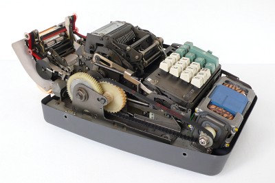
The two pictures above shows two machines who reduce the speed with gears or with an nylon belt and gears.
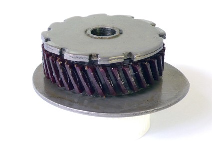
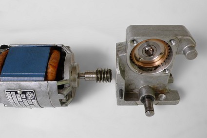
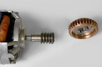
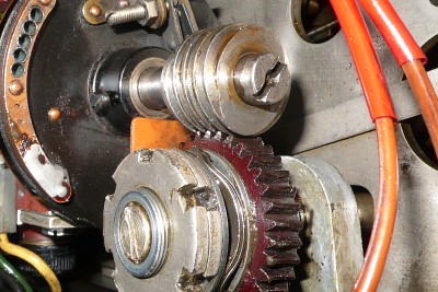
An other, often used way of speed reducing, is seen on the three photos on the left, they using a worm gear combination. Often this worm is hided in an aluminium house and that is filled with grease, but here it is nice to observe. It is very compact, strong and speed reducing from 1 : 35 is possible. The bigger gear is often of brass or
novotex / textolite a material made of reinforced bakelite (please see the the pictures below).
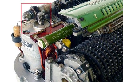
The second picture, direct to the left, shows a book keeping machine with three worm constructions, marked here with colored rectangles. The blue one is connected to the main axis, the red one to the movement of a carriage and the green one feeds the printing mechanism of the Alfa numerical keyboard.
A detail of the worm construction is showing the
novotex / textolite gear with a kind of safety mechanism in front. When the machine is blocked the motor power is stopped by this slipping mechanism or clutch. The spring plates are mounted under force, and the power where the slipping starts is set by the two screws in front.
But back to the design challenge: How to operate an electric motor to turn a machine axis precise one or multiple
360 degrees turns.
An catch and trap mechanism is used for it. Often this is a gear with square tooth, where a square catch is fit in (left picture). Turning is counter clock wise. At the start, the catch falls in the square gear and it is pulled out when the main axis has turned 360 degrees. (picture on the right) This gives the motor the possibility to roll out. Details we will see further on on this page.
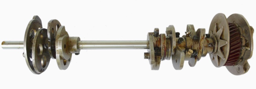
On the two pictures below we see the whole demounted motor unit and the mentioned clutch- and catch and trap mechanisms.
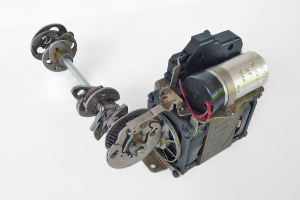
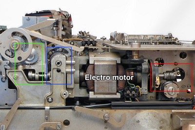
Here, to the left, we see the motor unit and the main axis from an Olivetti Divisumma 24. The worm gear makes the reduction in speed again and the catch and trap mechanism in front of the axis can be clearly seen.
Now we can see as well how many cam plates are used in such a automatic multiply and divide rocking segment machine.
The motor is a capacitor run type (please see the motor chapter).
Below we see the main axis separated from an other angle and we see the trap plate from the other side.
The clutch spring and the adjust nut is seen now as well.
Both the worm wheel with the attached cammplate and the plate with the catch mechanism below.
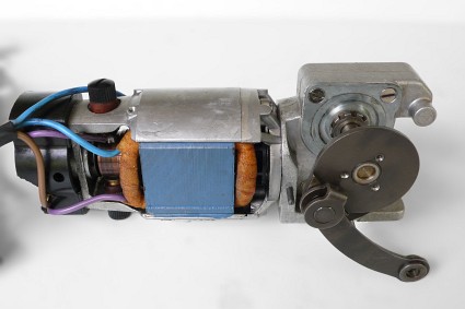
The Olympia 182-60 motor-worm combination below. The worm is hided in an aluminium house. Now open to explore. The same again but now with a bronze worm gear and more precise produced, like the Astra ones, with the curved gears. Please compare it with the Olivetti one above.
The trapezium gear form and this curve gives a stronger carry of force, both gear and worm touching each other on a larger points / surface. The last picture shows the catch and trap mechanism.
The whole again but now in a moving picture. It is the electric motor unit of an Ascota 110 or 314 etc . A typical example of a 360 degrees drive of the main calculator axis.
Below the Rokli A17E wich made a attanuation like a handel, only a part of the 360 degrees turn.