Speed Regulation
The first electrical driven motors are of the commutator principle and have no speed regulation by its self. Please see the menu item "Type of electric motors" above. Without a special limiting mechanism the speed running crazy and is mainly limited by their load. So to keep the speed within a certain range and far more independent of the load, mechanical speed regulators were build in. These regulators diver per manufacturer, but they nearly all are make use off the centrifugal force principle.
The centrifugal mechanism is mounted on an rotor plate. When the motor is turning low speeds, this switch is closed and the electrical power goes to the motor. When a maximum speed is reached the switch is opened by the centrifugal force. The motor will run slower and the switch will close again. This is a constant process and the switch has to be protected by spark avoiding network ( please see the special menu item on top). To be more accurate the switch is not turned the voltage off, but a power resistor in parallel with the switch take it over and provide a lower current supply. The big advantage is a lower voltage swing across the contacts (caused by switching off a coil / self inductance) and the motor is running much more smoothly.
Speed regulation on commutator motors
The first three pictures show early straight forward mechanisms of a speed regulation, with rotor coil switching.
The fourth and fifth picture use the same principle, but are in an other way constructed. The sixth is an stator switched type and they don't need slip ring and brushes anymore. The last three picture show the mechanical brake
type of regulation.
Mechanical brakes as speed regulator
Some manufactures uses mechanical brakes, as limitation of there motor speed. This is of coarse a principle only can be used in applications where the motor is only a short time active. You might say that this was correct for the first calculators built.
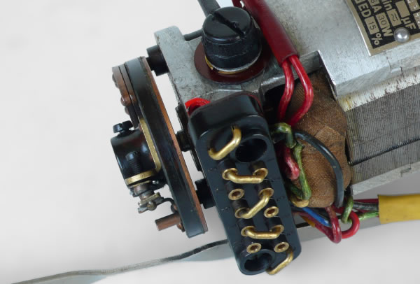
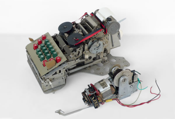
The first solution of speed regulation we see to the left on an ASTRA 110 machine with the motor separated from the machine. The electrical network is separated from the motor. That's why the cables have open ends.
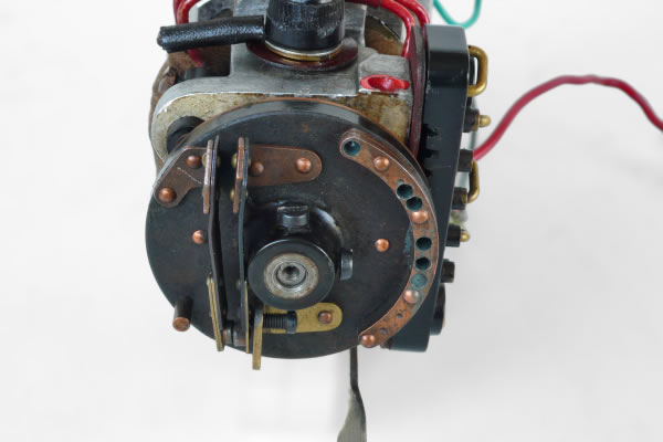
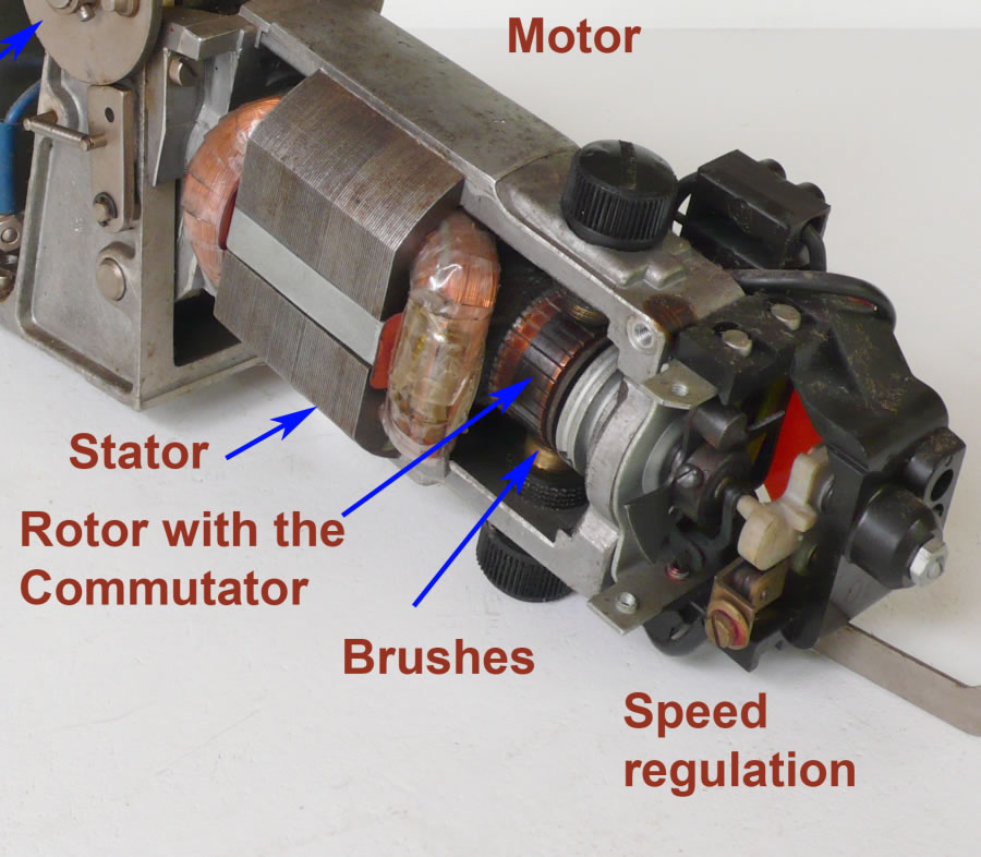
The motor and especially the speed regulator, in close up. The speed regulator mechanism is located on the left hand side. It consist of a plastic plate screwed on the motor shaft. The switch on top is connected via two slip ring brushes on the motor side on the plate. The plastic plate has two concentric rings of copper on that side, the slip rings. This to connect the turning switch with the rotor coil.
The black parts between the motor and the plate are the brushes.
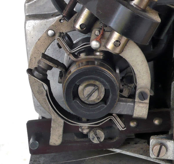
On the front side of the speed regulating device the switch is clearly distinguishable. With the screw below the centre the speed can be set. On the right the counter weight is located. When the motor starts turning the left hand side of the switch is more and more pushed to the outside of the plate and finally disconnects.
There are various embodiments of the mechanical speed regulators. Later versions didn't had the slip ring parts. They had a plate or a part of nylon, who is pushed to the front on the central axis. A non turning switch is operated then and regulates the supply of the stator coils current. You can see it fi at pictures on this side of later ASTRA and MADAS calculators.
The speed of capacitor aided / supported motors
At motors where capacitors are used to make a phase shift and the modern one phase induction motors (washing machines etc.), we see no mechanical speed regulator mechanisms. It is not needed there the speed is limited here by the net frequency. This motor has an different driving principle, as you can see at the chapter "Type of electric motors" above. The current phase shift, causes by the capacitor in one of the stator coils, does the motor start turning. The motor speed / the number of revolutions is determined by the net frequency. Depending of the type of capacitor configuration the aided capacitor is switched of when the motor is turning or it stay's on.
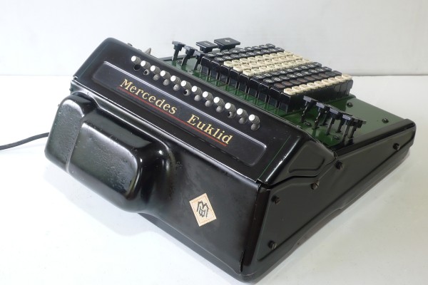
An example machine where the motor has a brake as speed regulator is this Mercedes 29
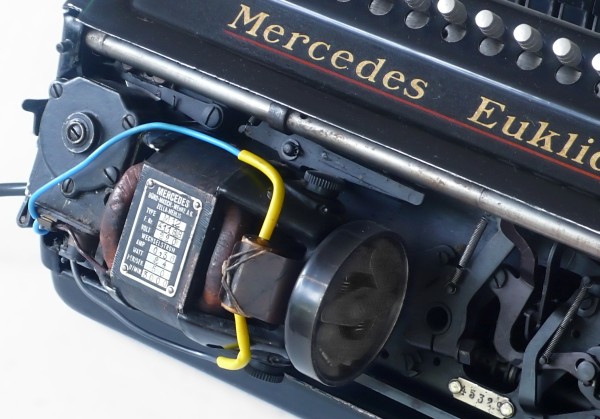
The back plate removed we see the brake in the cylinder to the right hand side of the motor
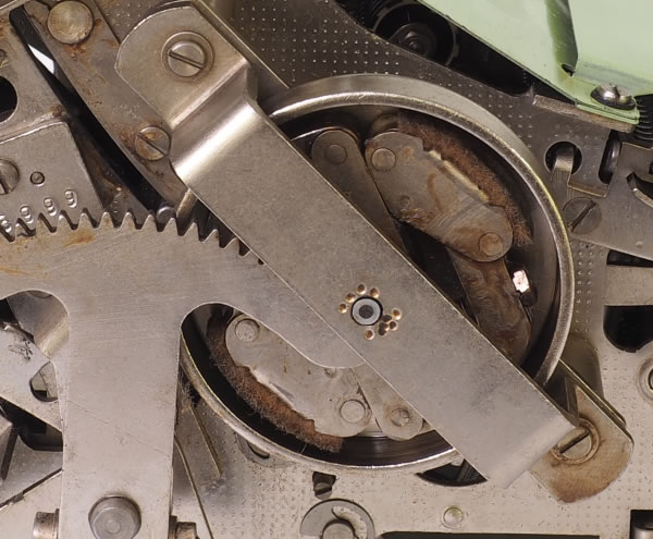
A better picture of the brake is shown here. The handle type of the Mercedes calculators had this brake as well for the same reason, to prevent to fast operation.
When the turning speed is to fast, the brake shoos, made of cork or felt, are pushed against the inner side of the cylinder. With the result of friction which brakes the speed.
At the manual operating machine they used this mechanism as speed brake in stead of the oil shock brake type of construction which we often see.
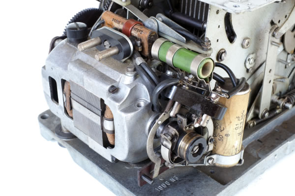
An other example from the same type. Here the brushes and the slip ring is clearly seen. The power resistor in green as well.
The switch here is symmetrically constructed. So it has in fact two contact brakes, which is good for the gap between the contacts and the spark prevention. (Have to bridge a greater air span). Here you see more clearly that the switch contacts are enforced by spring steel plates to withstand the centrifugal force.
The slip ring are in fact not necessary at all. In the early days the idee was to swish the rotor for that purpose, but why not do the same with the stator coils? Due to early magnetic stator iron I suppose, but the real design consideration is not clear to me.
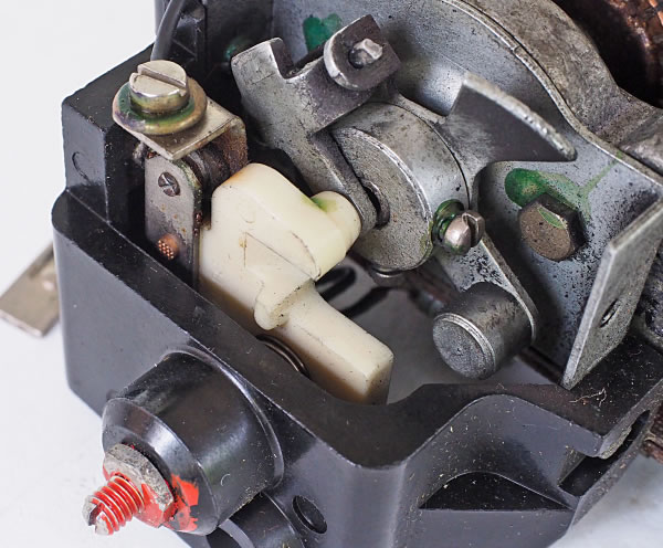
Below we see the type of mechanism which is used until the capacitor aide motors made their appearance.
Immediately on the motor axis we see a fan for obvious cooling reasons. Directly beside that a hinged and bended metal plate. The middle part is push to the right when the motor starts to turn. This pushes the white nylon part, which controls on his task the switches, locate below this nylon part.
As I wrote the stator coils are switched and no slip ring is needed any more.
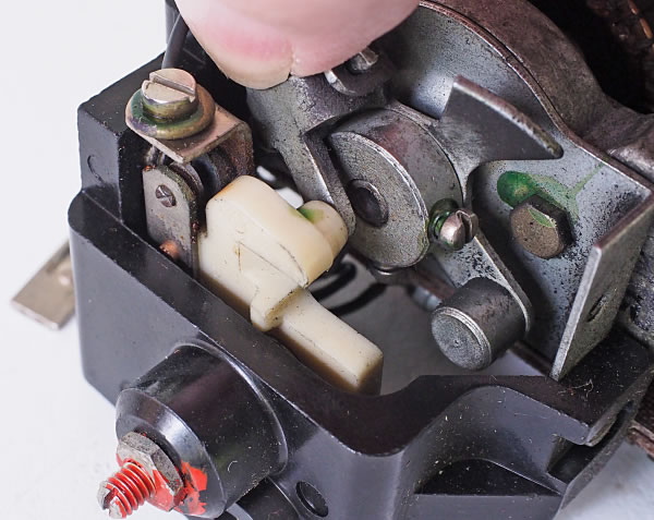
For those who like to have a little more detail:
Here the same mechanism from an other motor but the details are better shown. The tipper and the pushing mechanism, located in the middle of the picture, is in the state of low speed. That's why the switch, located on the left, is closed.
Here I push the tipper, simulating the centrifugal force on the tipper, in the fast speed state, and the switch opens.