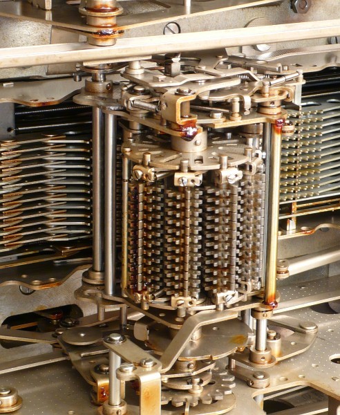
To stack those registers in a drum or carrousel, you have the possibility to use more registers. This is an example of the 5 registers in a book keeping machine, the ASTRA 150. To select the register you have to activate the turning mechanism, on the picture above and below the drum, as many sectors corresponding with the requested register. Then the register is pushed on the, data bus, on the picture behind, to communicate with a calculating unit or a print unit.
The various implementation of memories in mechanical calculators
Introduction
For instance at an automatic multiplication, we need an extra memory, or an second "register" as they are called it those days. We have to store first the multiplier, before the multiplicand can be entered. At calculations when we like to use the result of a previous calculation, in the next calculation, we need an extra register as well. In bookkeeping machines we need often more registers to store numbers which we need many times, like a tax percentage ore discount percentages etc. The maximum amount of registers, I came across in these machines is 55.
All these examples use registers to store numbers with many (8 to 20) digits. The mechanisms used at these type of registers differ. The different calculation technology (please see the chapter: "How do they calculate") fit different register mechanisms. In the next chapters I will show a few characteristic type of mechanisms.
How to store a number mechanically
As mentioned we have different type of registers, depending on the way they are used or you might say stored and read out / write and read.
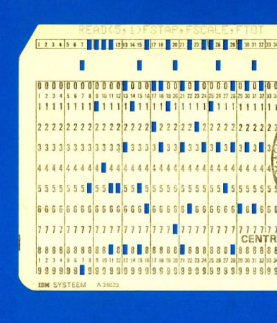
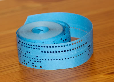
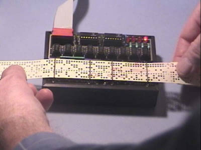
Paper tapes or punch cards
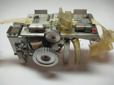
Beside these above mentioned internal used mechanisms, Paper tapes or punch cards as outside controls or memory were used at bookkeeping machines.
Special units were used to read this paper cards and tapes and make the connection with the central data buss. Later this connection is electrical accomplished.
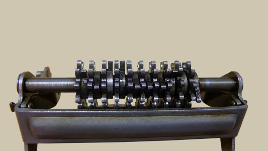
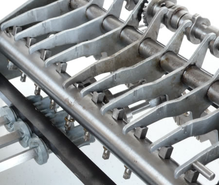
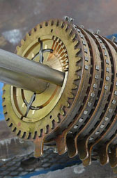
Stepped drum
An other mechanism we can use is the stepped drum. A bit unusual perhaps but we see it used at the Madas machines. (Normally at the calculation the top gearwheel is shifted longitudinal.) Now in a other stepped drum configuration, each stepped drum wheel is sensored longitudinal, from the front. The distance to the bar on the stepped drum, is the indication for each individual register digit. Please keep in mind that we use an multiplicand register per digit at a multiplication. First we use the first digit to multiply, than the second etc.
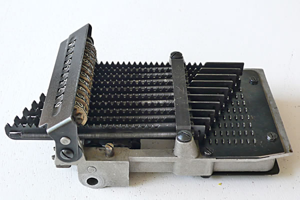
The pin box is used at the 10 key rocking segment machines to store the keyboard entry. On the picture to the left it used to show the keyboard entry as well with an extra display.
The rack as such can be used as memory as well. For instance in Olivetti Divisumma there are two memories implemented like that. A special gear rack with two gears per digit is used to make the connection the the central data bus and the rack.
The "How do they calculate" chapter explains that a rack gear is used to realize a result register. The number of digits
is determined by number of gearwheels in the rack. On the left we see a register of 10 digits.
At a closer look to the individual gears we see the null knock's on the right of the gearwheels.
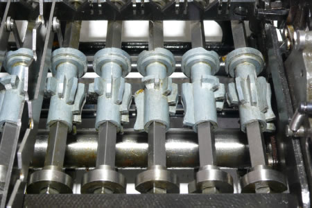
The mechanism to control this procedure is showed on this picture. The camshaft controls which digit has to be scanned. The shaft in front is turning until the active pen is reaching the stepped drum knock. This turning angle represents the value of the scanned digit.
The Pinwheel
The slider inputted pin wheel is of cause as well a mechanical memory of the multiplicand.
To be continued