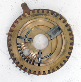
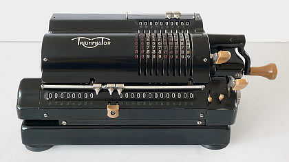
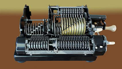
The haert of the machines above is Pin Wheel cylinder, as shown on the inside photo to the right, as the big brass part. The number wheel below the Pin Wheel is given de result of the calculation is the carriage and can be moved horizontally. The display above the Pin Wheel displays the Pin Wheel setting of the sliders, the input number.
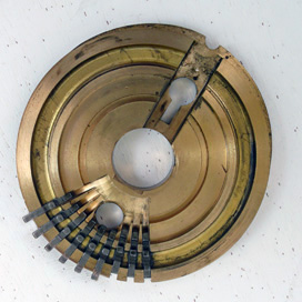
The Pin Wheel consists of many disks with a lot of commonality, but the disks differs as far the slider and pins angle is concerns. The picture to left is an animated gif showing the principle of the disks inside. Shifting the slider is putting an equivalent number of pins to the adjacent site of the disc.
Don't bother the shift direction, which is down for increasing numbers.
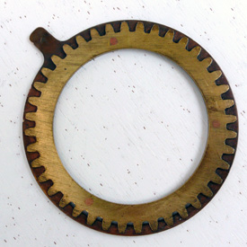
The four photo's around here showing the inside of a disk. To the left the front of the disk.
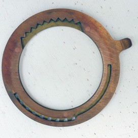
Below there is the disk dismantled, a ring took off. The first and second to left below, is showing that ring, the middle bottom up. To that picture below you see the guide groove of the ridges. The ridge parts have an up ridge which fit in that groove.
The gear on the disk will turn the input display above the Pin Wheel, when the Pin Wheel is in the idle position. Turning the slider will turn the groove an shift the knocks in- or outside the disk.
The outside ridges will fit in the gears of the display result number gearwheel. Turning the Pin Wheel
will turn that display gearwheel with the equivalent teeth / numbers. That number is added to the result. The adding is half way carried out. We didn't take care of the tens carry. How is that done?
To give you a detailed explanation of that, we need to have a closer look to the number wheels and the aligning up of the various ridges and gears, but that will showed on the page 2.