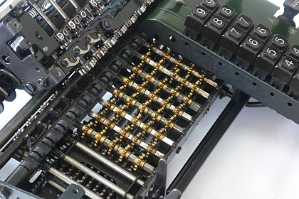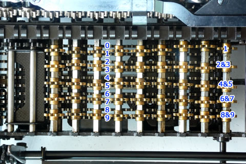
On the photo to the left you see the ten racks below the brass gearwheels. The racks are numbered on the picture from 0 to 9. The 0 rack is fixed. The other moved according the proportional lever.
The gearwheels, four for every digit, can be shifted of and on the racks by the key board unit, and turned on square axis, by the racks.
There is chosen for four gearwheels, because this benefits the shift distance. The keyboard unit has to shift each brass gearwheel either to the rack above or down to make contact with a rack or not.
Of course one of the four gearwheel at the time is put on one of the ten racks per digit.
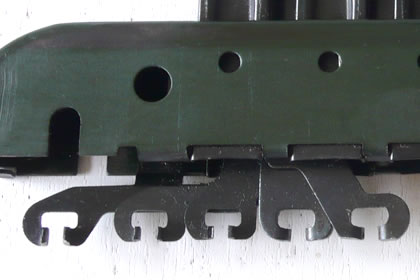
The lever is not seen, but is located under the racks and can be seen from the bottom site video to the left below.
Below the main axis, you will see the ten racks now from the bottom side. You would probably expect a video from the lever mechanism from the top, but with no support of the key units, who set the positions of the gearwheels it is hardly possible to do this without get blocked by a wrong combination of gears. The way the brass gearwheels are put in position is shown below.
Back to the video: You see that the racks move to the right and back to the idle position. The gearwheels on the square axis will stay on the racks during both directions. An row of intermediate gearwheels, between the result register, is only put on the square axis gearwheels during the forward movement and turn of off it, at the maximum deflection. This will turn the result register gearwheels with the number of teeth and prevent that the same number of teeth turn back, with no turn in the end.
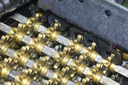
Now to the details on the shifting of the brass gearwheels by the keyboard.
First when no key is pressed the upper gearwheel stays on the upper rack, the fixed one at all time.
When there is a key pressed, the first gearwheel is leaving the fixed rack, setting the square axis free, and according the key which is pressed one of the others will put on a rack. For instance when the nine is pressed, the lowest brass gearwheel is shifted to the lowest rack.
The not supported other gearwheel showed in the idle position.
Here the whole sequence on video. Started off in the idle situation, followed with the key's 1 to 9 and end in the idle situation again.