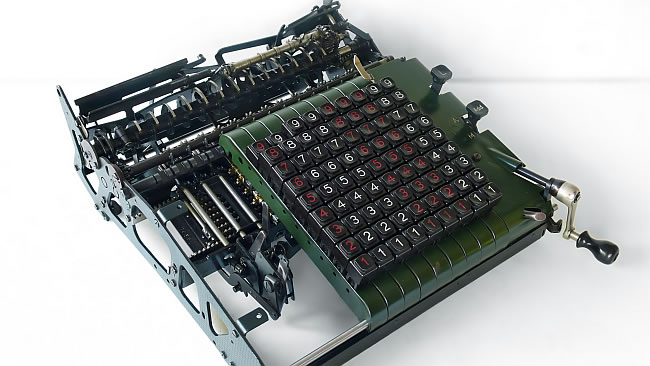
Continuing the theory of how the Proportional Lever machines get their job done, I have a 29 relieved from its carriage, as you can see on the two pictures to the left. This to get a better view on the intermediate- or coupling wheel. This mechanism connects the proportional Lever turning to the display gearwheels.
As we saw on page one, the based gearwheels turn the number of teeth of the key which is pressed, but turn back the same teeth. So the intermediate gearwheel should disconnect at the maximum swing to prevent no turn effect at all.
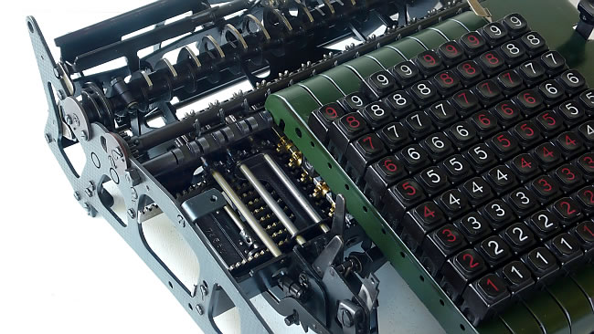
But first: Where do we find that intermediate gearwheel or better the gearwheel row. On the second picture we see it right above the key board units. We see only the two teeth of the gearwheels which are mounted in a turn able axis. In the idle state this gearwheel is not connected with any gearwheel. When the proportional lever is started to swing the axis starts to turn and push the intermediate gearwheel between the proportional lever and display gearwheel. (The later is off course not on the picture). The video's below will provide you with more details.
In this video we see this whole sequence happening twice. The intermediate row of wheels is at the top. We see before the Proportional Lever racks start to swing the row gearwheels is turn towards the Prop.lever gearwheel, which can be found down the row. (better seen on the next video)
This video, which it is taken from the backside, shows it better.
How the gearwheel row is turned in the way is does, is controlled by the gearwheel mechanism whish is showed here.
The axis below is driving a partly reared wheel. This is turning the axis with a even complicated wheel. Both happens to the right of the screen.