His idea was:
"Lets make block with an array of press able pins. The pins columns are pressed by one of the 10 key's (0-9).
Shift the block, after a key is pressed, one position. So the next column can be pressed, being the next digit of the number".
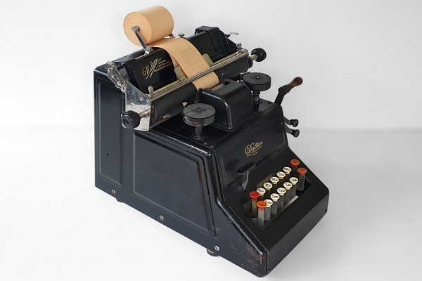
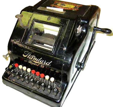
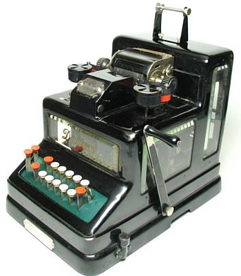
This mechanism is applied for the first time by the Standard Adding Machine Company (picture on the left), founded by Mr. William Hubert Hopkins. Mr Hopkins is soon after moved to the Dalton Adding machines Company and they built (1902) very successfully machines with the 10 key mechanism (picture below left).
Both machines differ in lay outing the keyboard, the Standard has one- and the Dalton has two lines of figures.
In 1920 the mechanism was reliable for volume production.
The technology is used from that year on by other US companies Remington and Burroughs as well.
Remington, by the way, bought the Dalton Adding Company on the same year.
Sundstrand is using the mechanism as well but in their machines the the pin push mechanism turns in front of the pin block and the pin block its self stand still.
The main developer and founder of the German company Astra, Mr. Greve, came in 1922 (after a few years stay at the Dalton company) with the first European concept, a three line keyboard.
You might think he was positively impacted by the Hopkins and Sundstrands mechanisms, although Mr. Greve 's concept differs from both. The pin block is flat and in an up ride position as the scanning tooth racks are. The pins where pressed by 2mm thick wire extensions of the key's. The German name of the whole mechanism is: "Stelt Stift Wagen". (please see pictures later on in this chapter)
To the left the complete later version of the Dalton little giant machine.
We see the zero key back again. At the full keyboard the zero was default, but here we need the zero for in stands at a 203. The middle zero has to be entered.
Here we see one of the segment gears, which is located above the pin block. The register gear below to the right and the rock which stops against the pressed pins on the left below. The pin block, with just one key pressed is drawn schematically below.
The machine handle activation will start turning the segment gear to the left and therefor moving to the right. Prior to that the register gear is put on the segment gear. The segment is turning CCW until it meets a pin, of a pressed key, and stops turning.
We see on the picture, to the right / top that on the segment is the printing part mounted. This will in case of a nine maximal turned and stand out of the machine. This corresponds with the our observations, when we printing a nine.
The zero is in the higher end of the printing part and results in no turn of the segment and no stand out of the print part.
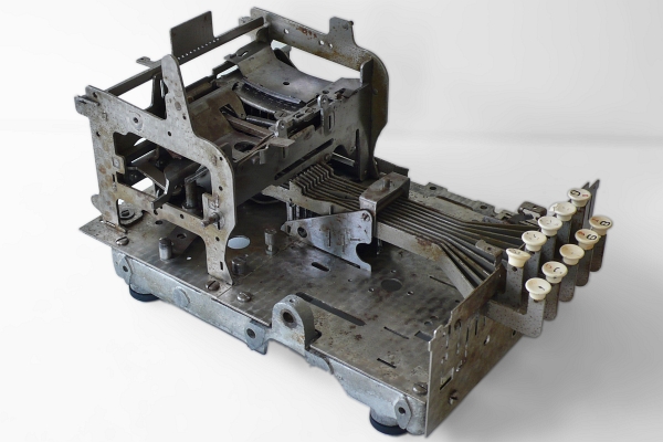
On this picture the bottom plate with the key's and the pin block mechanism. The mechanism is in the rest position and is hidden. We see the key extension bars.
When a key is pressed we see on the other end of its bar that it will push the corresponding pin out of the pin block.
The pin block is now shifted out. We see a rounded base shape and a number of pins stand out. Again one per row.
A closer look is given on the next picture.
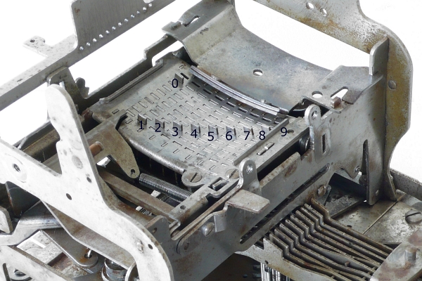
The numbers are the values of the pressed keys. You probably noticed that this pin block has the representation of the complete number which is entered like the full key board had.
On the Dalton machine the nine has no pin but a bar, like on the full key boards. We see that the surface is not flat but has a rounded shape. The reason is the segment gear, which has the turning point above the pin block.
The Astra machine has in fact not a gear segment but a straight line toothed bar (see picture farther below), which is shifted vertically beside the block of pins.
The pin block from the Astra machine. We have a view from the key board side. We see in this demo just one key wire extension. We see the nine holes for the other wires forming the row of the ten key's. We see the unpressed pins. The block is transported row by row on the two bars. The mechanism which is doing this in the right distances is seen on the top bar. It is compatible with the system of a pedal clock ticker. (not well shown in this picture)
Here we have one of the straight tooth bars of the Astra machine. The rock, which is scanning the pin block vertically from bottom to top, is stopped by the pin which is active for that digit.
This tooth bar is vertically mounted. (turned 90 degree ccw) in the machine.
The 10 key mechanism of a ASTRA, Olympia and Sundstrand machine
Later Astra machines like the Astra Klasse 110 have put the pin block horizontal and have a multiplication features on board. As is written in the general page of the Rocking Segment technology the shifting of the pin block can be used for repeat adding of each digit of the multiplicand. The Astra 110 has a special key R+ who has to be hold as many cycles the particular figure of the digit value is. After that the pin block is shifted on position to be ready for the next digit of the multiplicand. More on the Multiply chapter.
Above the Astra pin block in a very dismantled state. Below you will see the key board unit, including the pin block of a Olympia machine. The Flash movie shows the other side of the pin block. The expected pins come through, from zero to 8 and a pin which indicate a pressed key (the one on the top row).
The scanning of the block is started by first move the block to the front and is executed the from top to bottom. A nine scanning is stopped by the plate below the pin block.
Please push the white triangle below, to start the movie.
An perfect animation of a ten Key machine by : Michael L. Hilton, via You Tube.
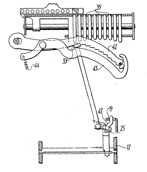
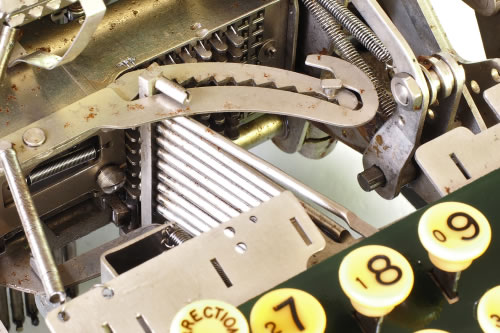
The Sundstrand ten key mechanism
Although developed in roughly the same time frame, the Sundstrand ten key mechanism differs from all the others. Here the pin block is fixed and the pushing mechanism is moving, or more precise turning. The pushing mechanism, hinged connected with the keys press mechanism, turns in front of the circular shaped (different length of pins) of the pin block.
The mechanism is clearly open to follow from above in the open machine.
(please see the video's below as well)
The drawing below is a part of a later patent but shows the mechanism from above.
Sundstrands key layout was different as well. It is the one which became standard over the whole world.
My first idea was that the scanning mechanism, which is reading out the pin block (which pin is pushed in?) could be the same as for the moving block configuration. But it is not. The scanning mechanism, which is shown on the top of the drawing, is hinged connected with shifted arms / levers, not showed on the picture. (Please see the video's below.)
As I said taught for the basic working of an add it is not needed that the scanning is turning as well. But in the next page (top menu) it is explained more in detail, with a subsequent adding you can perform a multiply. For that subsequent addition you have to entering an zero, after each series of adding of the subsequent digits of the multiplier.
So for that a shiftable scanning is needed.
At the Sundstrand
mechanism it is a rather complicated scanning mechanism, but they keep it still in the models they patented in 1954, although the rest of the world is using the shiftable pin block.
Rocking Segment Mechanism (page 3)
Ten Key Keyboards the Introduction / resume
On the first page, of this Rocking Segment section, we saw the full keyboard, where the "9 key columns" are used to enter the subsequent figures of the complete number, creating a series of pins. In 1901 Mr. William Hubert Hopkins (St. Louis USA) invented a ten key keyboard.
With the big advantage of improving input speed and make smaller machines possible.
The ten key mechanisms explained in detail
The Dalton used mechanism
The first video is taken from above. The configuration is as drawn. The second video is taken from the bottom site. So please take that in to account when you try to understand what you see. The main focus is on the 2e video on the scanning mechanism and the way the extended levers turn and shift.