The actual, simplified, multiplications works as follows:
On this more in detail picture, you see the register is hold position by a plate with steps (On top, mid of the picture). This plate turns to the right and the multiplicand register moves one digit at each step upwards. This is used to sequential access each individual digit of the multiplicand. As often said a multiplication is repetitive additions, so as long the first digit is not zero, an addition of the pin block content, to the total register, is performed and this multiplicand digit is with one decreased. When the first digit reaches zero the multiplicand register shifts one step to the next digit to determine the adds of the tens, the pin block is shifted one position as well. Like so for the hundreds etc. The pin block size is limited so the multiplicand is.
The Astra 110 has a "R+" key. Holding down that key, will add the content of the key board / pin box, each cycle to the result register. After those cycles the SSW shift one position to the left. So the next time pushing and holding the R+ key for instance 2 cycles, it multiplies times 20. Next p X 100 etc. You have the possibility to do so until the SSW comes in the end position. With that we have a limiting factor of this way of using this Rocket Segment technology for multiplication.
When you don't like to print each individual adding of this multiplication procedure, there is a somewhat hidden key / switch to turn it off (on the side to the left, down near the cap release).
Mechanical "Data buss" and the link with to days computer architecture
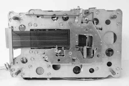
We know data busses in current computers as common medium between for instance the CPU and memory. They are transporting digital signals, ones and zeros, between the digital computer parts / units. In rocking segment machines, with more complex functions implemented, such as used in bookkeeping machines, manufacturer like Astra / Ascota used the word data buss for the horizontal gear rack as well (as seen picture below) a decimal values data bus. This is a clever way of looking to the machines. Why not see the racks as a connection between the calculator unit (CPU) and the printing unit, as shown on second the picture below. In fact and I like to refer to the manufacturer chapters of the Astra Ascota 314 and 170 for more pictures, you may seen the keyboard as well connected to the data buss.
The 170 has several peripherals like a external memory, a punch card- and punch band reader, a divider and multiplication unit who all have access to this central data buss, the racks.
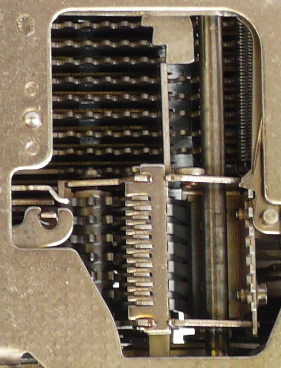
You may have noticed that the racks can be modified as well. The right part is at this version having no teeth on the side we see it on the photo, it is however possible to use the same bar as on the left part is used to extend the number of units to access the data bus. (The upper part has teeth, register K is located there.) This possibility is clearly shown by the side walls of the racks. They have the holes to mount many more units on the buss. Good example of modular design in the 1950 thy's.
A video showing the manual multiplication of 45 times 12345679 by adding a zero to the multiplicant
A video showing an automatic divide of 555555555 by 45 is 12345679. More information how the calculation is done