Switched Latch Wheel
Introduction
The principle of a Switched Latch Wheel has been discovered by Leupold in 1727, but is known in the world as a technology designed produced by mr. C. Hamann. The machines named Hamann Manus. No other manufacturer had ever used or licensed the technology.
(when some one now's differently, please let me know!).
The machines are robust, reliable and ability to automate division and multiplication, gave these machines a tremendous market share. At the first occasion you will think it is a pinwheel machine, it isn't. The difference is immediately clear when you see them operate. The sliders don't turning, when the crank turning and at all the calculating types the crank is turned in the same direction. From 1925 on the machines are on the market. Continually improving the functions resulting in a pallet of type numbers, but the basic technology remains the same.
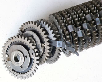
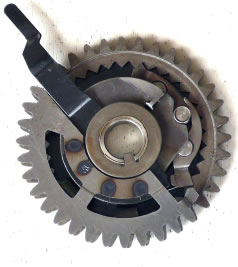
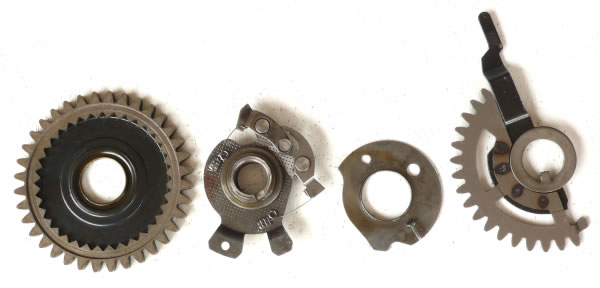
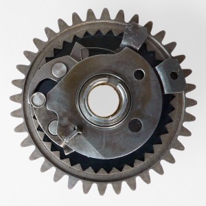
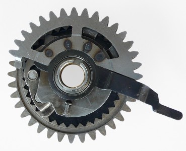
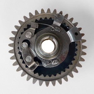
Direct above to the left we see one complete unit of the switching latch wheel, to the right a dismantled one. On that last picture we see from left to right the four separate turning plates of the switching latch wheel. The first plate / gear has in site triangle teeth for the latches. The latches are mounted on the second plate. This plate is fixed to the main axis and following the calculator crank axis. The third plate is fixed to the base of the machine and is used as plate for the roll to follow and the latch steering. The roller of the latches is following this camplate together with the fourth plate. Both they determents the begin and end position of the latch position, with other words where the latch is fixed to inner triangle of the big gear.
The technology in a nutshell
By setting the sliders, input a figure / number, a mechanism is sets so that, by each turn of the crank, the big gearwheel is turning an equivalent number of teeth.
The same, but some what more detail
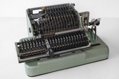
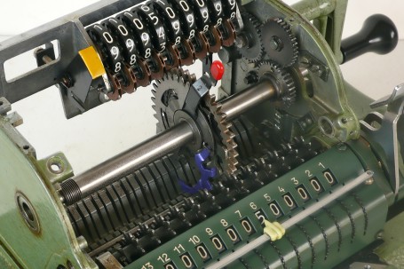
An open Hamann Manus R is showed on the picture, below to the left. We see the carriage in the front, which is usual at pinwheel machines as well. Above the carriage we see in line a number of bigger gearwheels. Those gearwheels are separate units, one for each digit, containing the switching latch wheels. One unit has four separate turning plates, mounted on the central / crank axis. The picture on the right shows the dismantled units.
The slider, used to set the input numbers, is mounted on one of those plates with a part outside small and bigger circle. An other plate, with the same outside circles dimensions, is placed next to it. A roller is placed on the side of these circular plates So that the roller following a certain part of the turn the smaller circle and the rest of the turn the bigger circle. That part is set by the slider. The hinged connected latch clicks in the inner triangle of the bigger gear when the roller is following the smaller circle. When the roller is following the bigger circle, the latch is disconnected from the internals of the bigger gear.
This results is turning the bigger gear with the that number of teeth the slider is placed on. This will fed the register gears on the carriage.
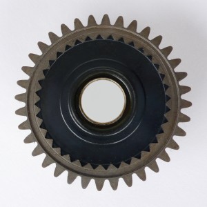
Building the plates together again shows plate of the big gear first. The second is the plate with the latches mounted. We see that the latch is in fact double (left on the picture). The roller is in the middle of the picture to the left.
The two latches are pushed into the triangle inner gear by the smaller springs.
Now we see plate three mounted. This is one of the plates the roller is following (the inner circle) and we see the latch active.
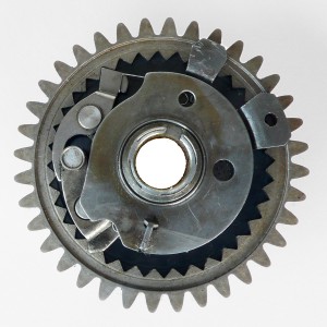
On picture four, plate three is pushing the roller out and the latches free from the triangle gear.
Be aware in the real situation plate three stays still and the roller / latch plate
is turning.
So when the latches are of the gearwheel this is not turning with plate three, when it is on the gear, the roller plate turns and the bigger gear is standing still.
So the gap between the falling edge (from outer to inner circle) of plate 3 and the razing edge (from inner to outer circle) of plate 4, is the period where the latch is connected to the big gear and the bigger gear will turn. This period is set by the input slider. The teeth on plate 4 are the same as those on the bigger gear, so perfect for control the exact position of the slider setting.
This was an explanation showing the essentials of the Switch Latch Wheel technology. In the Hamann machines there are around switch latch wheel units a few bars etc. An example of that we see in the assembled Hamann R with just one unit on the pictures below.
Here we see on picture 5 the same situation as picture three.
The latches are active.
On picture 6 the slider plate is mounted. The black plate is the outside circle plate (the black plate of plate 4). So when the roller is reaching that position, it will follow the outer circle of plate 4, in a not latched situation.
Links to more on the Switching Latch Wheel technology:
A small anchor (blue colored) is connected to the plate three to hold plate three on his position fixed to the machine bottom plate. This anchor is shifted in plate three.
The input counter above, is directly connected to the slider. Due to the tin thickness of the slider plate, the gear is having side plates to prevent slipping of gears.
The bigger gear is directly feeding the register gears in the carriage.
So far we didn't care about the carry. That will be explained in page two in a few weeks time.