General
Adds and subtracts are in mechanical calculators executed in one turn of the crank or motor. In general terms we call it in "one cycle". Multiplies are executed as multiple adds, so in multiple cycles. This automat machine does these multiple cycles in a sequence of subtracting each digit of the multiplicand register, and performs an add of the keyboard entry to the carriage, the total register. This until the multiplicand digit reaches zero. Now an shift to the next digit of the multiplicand register is done and the carriage is shifted one position as well. This sequence is performed until the last multiplicand digit is zero.
You will understand that automation all this is obvious.
What do we need at a Multiply?
We need at leased two separate input numbers. So beside the keyboard input we need an extra input, an multiplicand register, to store it until the second number is ready at the keyboard. At the Madas it is located in front of the machine, just below the keyboard. It can be set manually, with the front knobs or via the keyboard by pressing the number and the multiplication-bar for the transport to the multiplicand register. This can be fillet with the content of the result register as well.
We need a mechanism to determine the content of this multiplicand register an finally we need the carriage shift control.
How is the multiplicand register read-out.
Before giving you the answer, we first have to realize: "What do we do with the multiplicand content?" We need it to execute the multiple add per digit at an multiply.
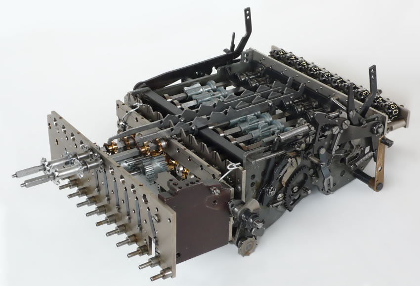
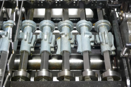
This is done with an smaller set of stepped drums, again one per digit. These are located below the key board. On the picture above all the digits are seen. The picture below we see them in detail.
Stepped drum. Automatic multiply mechanism (on the Madas 20AV)
The readout is not done as usual at stepped drum machines, instead the length of the teeth is used to determine the number of additions. Below the stepped drums a pin shaft is located. (pins are hide behind the stepped drums)
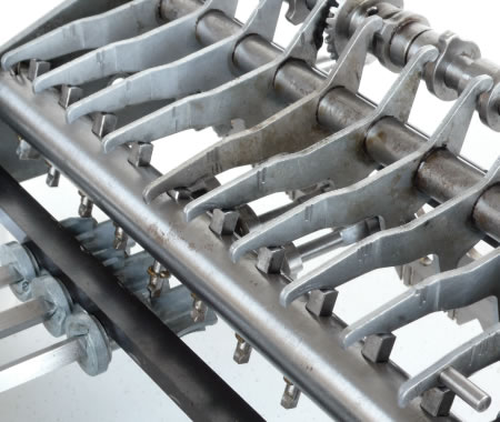
now it more clear. I have dismantled the multiply unit a little bit more.
This pin shaft is having pins to protrude, who are actuated by an cam lever, which is engaged by a cam shaft (right). When the multiplying process needs the figure of the digit, the cam shaft has a cam. The cam lever pushes the corresponding pin in the shaft. Here the 5e from left. On the other side of the pin shaft the active pin is protrude. The pin is bumping against the stepped drum tooth top.
Here the pin shaft is in the rest position. Please notice the gear wheel, in the front right. This is where a ratchet system is counting backwards, from the situation on the previous and the next picture, to this rest / zero position.
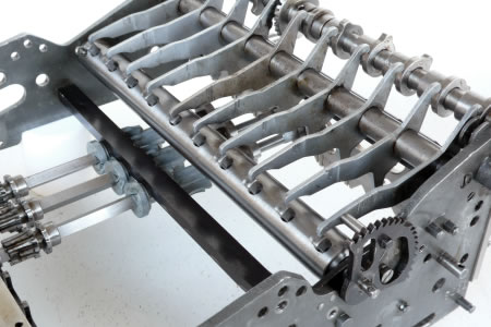
Here we see the active pin again bumping against an tooth of the stepped drum and we see that the gear wheel is turned. In other words: "The number of teeth the pin shaft is turned is kept in the gearwheel. A ratchet mechanism (not seen on the picture!) is turning this back. At each count an add will be executed. This until the gear wheel is in the rest / begin position. The carriage makes one shift to the next higher digit. The next digit / the next stepped rum is read out, the same sequence again: Camshaft is pushing the next lever down. The pin shaft is turning. The next pin above the next stepped drum is read out. The gearwheel is turning back by the ratchet mechanism, and the number of adds are executed followed by a shift of the carriage.
This until the last significant digit of the multiplicand.
Just one note: Is the longest tooth is the zero, no gear wheel turn. The shortest tooth is the nine. Logical! Please remember the number of adds. It is the same with the adding gearwheels, there is the longest the one as well.
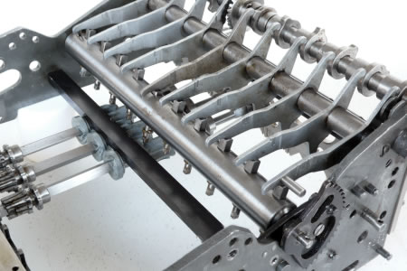
This Madas 20AV is a full automatic mechanical calculator (pictures are from the back of the machine). The internal add unit (left on the picture) and the multiplier unit (on the right / back side). The Add unit has for demonstration purposes only two digits. In the machine the units are mounted on the frame, here the two units are guided by two pins to get them aligned. I tide then together with two metal wires.
Notes
Prior the Dismantled process
The whole second machine was blocked. A treatment of W40 and manual force to get thinks move was getting the basic add and subtract, cleaning of the registers and shifting the carriage back on track. The automatic multiply and division was not proper functioning. A few key activation on automatic multiply process was half ways stopped and nothing moved. A intensive try to find the cause was not successful. After a few day or so trying,I desisted to dismantled the machine for demonstration process.
A few reasons found of the blocked situation
At leased two shafts, with a chain of independent turn able cam levers, were not proper functioning and partly blocked to the shaft or the next neighbors, One shaft was the daisy chain, below the counter register of the carriage and the other was the shaft below the cam shaft on the picture above. The first was more or less cleaned on the open machine. The second I discovered during the dismantling process. Now the behavior of the machine during multiply is clear and corresponds with this failure.
A note:
Both failures were coursed by dried out oil and the same type of construction were oil refresh was not coming on those plashes were it is needed. The shaft had directly metal rings on it who had to move independently of the shaft and the neighbors rings. Often they were fixed to the shaft or to their neighbors.
Automatic Division
The automatic division was not functioning as well, but this function I didn't study at the dismantled process. The
web side of mr. John Wolff is having that well documented.